STM32
Published Aug 31, 2023
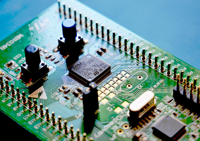
This guide details environment setup for programming STM32 microcontrollers (MCUs) and reviews general low-level functionality, such as configuring GPIO pins, peripherals, and interrupts. The ST website provides a listing of MCUs based on use case, e.g., “High Performance,” “Ultra Low Power.” However, if unsure about the specific project requirements, simply choose an option from the “Mainstream MCUs.”
All tutorials in this guide refer to the STM32 Nucleo-G431RB development board. We will also use the JetBrains CLion IDE instead of the STM32CubeIDE for all development. Source code for the tutorials may be found at github.com/lukasvasadi/stm32-tutorial-source.
Why use STM32?
STM32 microcontrollers are generally considered an industry standard technology, as opposed to Arduino, which, until the release of the Pro series, has served primarily an educational purpose. Compared to conventional Arduino boards, as well as the multitude of third-party MCU boards created for the Arduino platform, STM32 often provides more performance for substantially less cost. For example, the difference in processing speeds between ST and Arduino dev boards of similar costs can be upwards of 50 MHz.
What are the barriers to entry?
Over the years, especially with the introduction of Arduino, MCU development has become simpler and streamlined. This is due to greater abstraction, which no longer requires users to understand the build process. In the case of the Arduino and STM32Cube IDEs, the developer usually selects a board from a preconfigured list and presses “play” to build and flash the chipset.
However, while greater abstraction has certainly made STM32 development approachable, this platform still demands a greater level of understanding, both of the hardware and firmware, than Arduino. Specifically, STM32 development frequently involves configuring low-level pinout functions, clocks, and timers, as well as explicit reading and writing of registers. This can be a daunting task for inexperienced engineers and hobbyists, but with dedication and a little effort, the reward can be extraordinary.
Even though the STM32 platform requires a deeper understanding of hardware development, I have found that programming more advanced features, such as interrupts, is easier than Arduino.
This setup is suitable for Windows, Linux, and macOS. The main requirements are as follows:
- STM32CubeMX Graphical tool for configuring STM32 microcontrollers
- GNU ARM toolchain Cross-platform toolchain for compiling C/C++ source
- OpenOCD Open-source debugger software for microcontrollers
- CLion JetBrains IDE for C/C++ development (optional)
STM32CubeMX
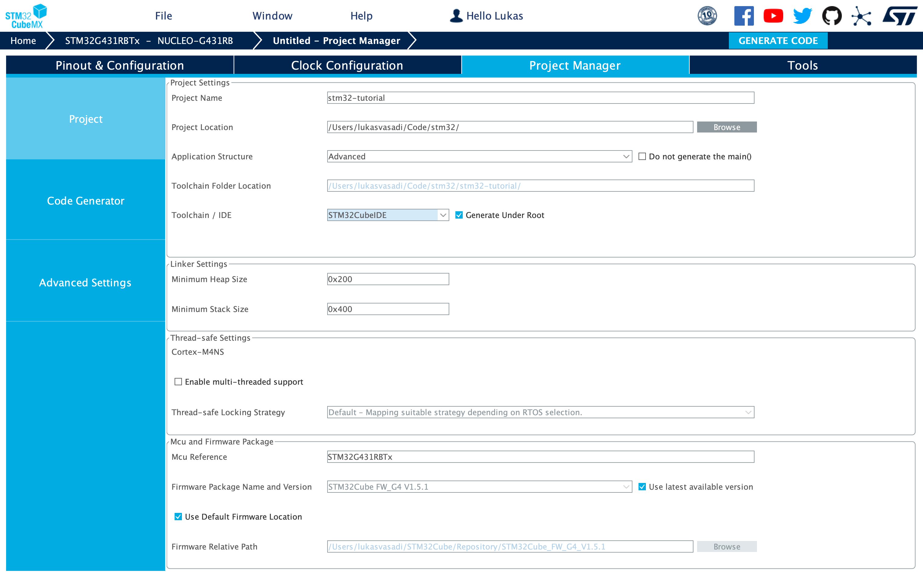
STM32CubeMX is a graphical tool that guides the user through standard project setup. Download and run the platform-specific installer from the product web page, but note that macOS may require additional permissions. If you have trouble, refer to the Readme.html document that ships with the software.
To configure a project, first select the chipset or board, e.g., the Nucleo-G431RB, and press “Start Project” in the upper right-hand corner, where you will be directed to a graphical representation of the MCU pinout.

In MCU pinout, green highlighting indicates that the pin has an assigned function, e.g., USART, GPIO. When a function is assigned, the user can modify its behavior through various options in the left-hand pane. As shown below, by default, pin PA5 is connected to the onboard green LED (LD2).

GNU Arm embedded toolchain
Windows
The GNU embedded toolchain for Arm microcontrollers can be installed via the executable from armDeveloper. Alternatively, install via Chocolatey:
choco install gcc-arm-embeddedLinux
sudo apt install gcc-arm-none-eabi gdb-multiarchmacOS
brew install --cask gcc-arm-embeddedOpenOCD
The Open On-Chip Debugger (OpenOCD) is an open-source software package for programming and debugging specific embedded hardware systems. It may be used to configure JetBrains CLion (see below) for STM32 development.
Windows
choco install openocdLinux
sudo apt install openocdmacOS
brew install openocdJetBrains CLion IDE
ST provides an Eclipse-based IDE (STM32CubeIDE) for its microcontrollers and development boards. This IDE integrates with the STM32CubeMX graphical tool for initializing MCU pin configurations. Although the ST-supported IDE has many platform-specific features, I prefer JetBrains CLion for its stronger C/C++ language support and cleaner UI. In addition, the JetBrains developers created seemless integration with STM32CubeMX. You can download the software with a free 30-day trial from jetbrains.com/clion.
A complete guide to configuring CLion for STM32 can be found at STM32CubeMX projects. Once you have installed the compiler toolchain and dependencies, and configured the IDE, you are ready to begin development!
With the default pin configuration, we have access to the onboard green LED (LD2) via GPIO PA5. To blink the LED, we need to modify the Core/Src/main.c file, specifically calling the pin toggle function in the infinite loop:
/* Infinite loop */
/* USER CODE BEGIN WHILE */
while (1) {
    HAL_GPIO_TogglePin(GPIOA, GPIO_PIN_5);
    HAL_Delay(2000);
    /* USER CODE END WHILE */

    /* USER CODE BEGIN 3 */
}
/* USER CODE END 3 */
In the above code sample, the “HAL” function prefix is an acronym for “Hardware Abstraction Layer,” which is a large ST library of convenience functions for controlling peripherals.
In this section, we will configure the Nucleo-G431RB for serial communication with interrupts. In the infinite loop, the MCU will continue running the blink routine from the example above, but upon receiving serial input, the processor will stop execution on the main thread and run a dedicated event handler function.
To begin, we have to contigure the pinout for USART1, which stands for “Universal Synchronous Asynchronous Receiver Transmitter.”

The example below shows the source code for interrupting the main thread based on incoming serial data. This data is then used to determine the toggle state of two GPIO pins.
/*
    Serial pin control
    Toggle GPIO pins based on serial input
*/

const uint8_t rx_data[2]

int main() {
    MX_GPIO_Init();
    MX_USART2_UART_Init();
    HAL_UART_Receive_IT(&huart2, rx_data, 2);
    HAL_GPIO_WritePin(GPIOA, GPIO_PIN_9, GPIO_PIN_RESET);
    HAL_GPIO_WritePin(GPIOA, GPIO_PIN_10, GPIO_PIN_RESET);

    while(1) {
        HAL_Delay(10);
    }
}

void HAL_UART_RxCpltCallback(UART_HandleTypeDef *huart) {
    // Prevent unused argument(s) compilation warnings
    UNUSED(huart);

    if (huart->Instance == USART2) {
        // Receive with interrupt
        HAL_UART_Receive_IT(&huart2, rx_data, 2);

        // Toggle pin 9 based on input from data buffer at position 0
        if (rx_data[0] == 49) HAL_GPIO_WritePin(GPIOA, GPIO_PIN_9, GPIO_PIN_SET);
        else HAL_GPIO_WritePin(GPIOA, GPIO_PIN_9, GPIO_PIN_RESET);

        // Toggle pin 10 based on input from data buffer at position 1
        if (rx_data[1] == 49) HAL_GPIO_WritePin(GPIOA, GPIO_PIN_10, GPIO_PIN_SET);
        else HAL_GPIO_WritePin(GPIOA, GPIO_PIN_10, GPIO_PIN_RESET);
    }
}In this section, we will configure the microcontroller digital-to-analog converter (DAC) peripheral to output an analog waveform based on a lookup table stored in direct memory access (DMA). Reading the voltage level from DMA to the DAC output register (DOC) completely sidesteps the CPU, preventing MCU throttling and improving speed.
The lookup table contains an array of unsigned integers corresponding to the voltage levels at each point in a waveform cycle (0, 2π). The length of the array corresponds to the signal resolution. The waveform frequency will depend on the MCU timer signal, which drives the transfer of data points from DMA to DOC. The DMA must be configured to operate in “circular mode” to produce a continuous output signal.
In this example, we will generate the data points in the CPU at startup; however, you may also generate the lookup table beforehand and add the data directly.
Calculating the lookup table
Below is a source code snippet that can be integrated into the MCU startup routine. It calculates an output voltage level, , based on the number of samples, , and DAC resolution, .
#include <stdint.h>
#include <math.h>
#include <stdio.h>

int main()
{
    const uint8_t N = 128;  // Number of sample points
    const uint8_t R = 12; // DAC resolution

    const float step = (2 * M_PI) / (N - 1);

    float T[n];
    float V[n];

    for (uint8_t i = 0; i < N; i++)
    {
        T[i] = i * step;
        V[i] = (sin(T[i]) + 1) * (pow(2, R) - 1);
        printf("%.6f\n", round(V[i]));
    }

    return 0;
}